Juniper EX Switch GRE Tunnels
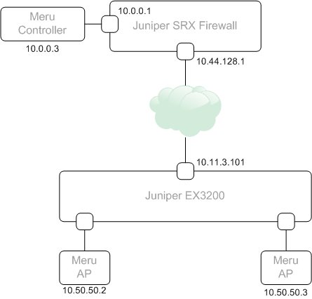
I recently had a need to establish a GRE tunnel between two sites. The reason being, we were deploying a Meru Wifi proof-of-concept where AP’s were on one site, and the controller on a remote site. Normally, the connectivity between AP’s the controller would go over the existing routed network (layer 3 mode in Meru-speak), but in this case, it wasn’t possible to get the new subnet assigned to the controller updated with the ISP providing the private links. As the customer was using Juniper EX switches and had a Juniper SRX firewall at the remote (controller) site, GRE allowed us to build the network without the need to involve the ISP.
The following topology was used –
GRE was added to the EX switch feature set in JunOS 12.1 (link here). In-order to use it, you need to allocate a physical port to be dedicated for tunnel services. For my example, I’ve used port ge-0/0/14 on the switch
set chassis fpc 0 pic 0 tunnel-port 14 tunnel-services
The JunOS 12.1 documentation above defines we allocate a port via it’s fpc and pic allocation. In my case, the switch was a single switch so the fpc was ‘0’. In a Virtual-Chassis environment, the fpc number would change. For example, if you wanted to use port 47 on switch 4, the command would be ‘set chassis fpc 4 pic 0 tunnel-port 47 tunnel-services’.
With the port allocated, we can then build the GRE configuration.
set interfaces gr-0/0/14 unit 0 tunnel source 10.11.3.101
set interfaces gr-0/0/14 unit 0 tunnel destination 10.44.128.1
set interfaces gr-0/0/14 unit 0 family inet address 10.11.12.1/24
On the SRX-side, the configuration is as follows.
set interfaces gr-0/0/0 unit 1 tunnel source 10.44.128.1
set interfaces gr-0/0/0 unit 1 tunnel destination 10.11.3.101
set interfaces gr-0/0/0 unit 1 family inet address 10.11.12.2/24
Each GRE interface has a tunnel source and destination set (this is the routed interface of the device at each end) and an inet address assigned to the interface which is used to establish the tunnel (10.11.12.1 and 10.11.12.2 in my case). I’ve used unit ‘1’ on my SRX, as I already have some GRE tunnels built to other destinations. A GRE interface uses the same unit assignment as a switch or inet port in JunOS, they can be used for different connection purposes.
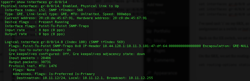
GRE tunnels show ‘UP’ immediately, even if the configuration isn’t set correctly, so don’t assume as it’s UP, it’s going to work. Look closely at the Input/Output packet count to validate traffic flow.
Here’s the output of ‘show interfaces gr-0/0/14.0’ on the EX.
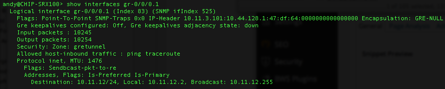
Now the output of ‘show interfaces gr-0/0/0.1’ on the SRX.
Back on the EX switch, we set routing-options to send any 10.0.0.0/24 traffic through the GRE tunnel.
set routing-options static route 10.0.0.0/24 next-hop gr-0/0/14.0
On the SRX, we set the routing-options to send any 10.50.50.0/24 traffic in the same manner.
set routing-options static route 10.50.50.0/24 next-hop gr-0/0/0.1
As the SRX is a firewall, we need to perform some additional steps to allow traffic. This means creating a ‘zone’ to assign the GRE tunnel interface too, disabling any Network Address Translation rules, and some security policies to permit the traffic. Here’s what I’ve configured.
set security policies from-zone gretunnel to-zone trust policy allowall match source-address any
set security policies from-zone gretunnel to-zone trust policy allowall match destination-address any
set security policies from-zone gretunnel to-zone trust policy allowall match application any
set security policies from-zone gretunnel to-zone trust policy allowall then permit
set security policies from-zone trust to-zone gretunnel policy allowall match source-address any
set security policies from-zone trust to-zone gretunnel policy allowall match destination-address any
set security policies from-zone trust to-zone gretunnel policy allowall match application any
set security policies from-zone trust to-zone gretunnel policy allowall then permit
set security zones security-zone gretunnel host-inbound-traffic system-services ping
set security zones security-zone gretunnel host-inbound-traffic system-services traceroute
set security zones security-zone gretunnel interfaces gr-0/0/0.1
set security nat source rule-set trust-to-gre from zone trust
set security nat source rule-set trust-to-gre to zone gretunnel
set security nat source rule-set trust-to-gre rule source-nat-off match source-address 0.0.0.0/0
set security nat source rule-set trust-to-gre rule source-nat-off then source-nat off
Now we should be able to initiate a traceroute from the EX switch to our Meru Controller (10.0.0.3).
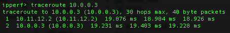
Looks good. We enter the GRE tunnel interface (10.11.12.2) and exit directly to the Meru Controller.